- Get link
- X
- Other Apps
Whenever bypass capacitor is connected in parallel with an emitter resistance the voltage gain of ce amplifier increases. Amplifiers are used to increase the voltage and current of a weak signal to desired levelthere are two types of amplifiersthey are given below.

Common Emitter Amplifier
Solved Consider The Typical Common Emitter Amplifier With

Common Emitter Amplifier Gain
In this case as phil points out there is emitter degeneration present which essentially reduces signal ac gain while increasing linearity.

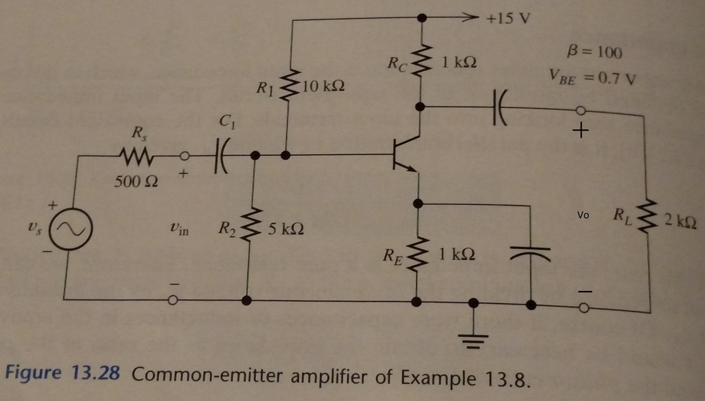
Common emitter amplifier emitter capacitor. This article discusses the working of the common emitter amplifier circuit and its applications. The reason for this can be seen from the fact that as the input voltage rises so the current increases through the base circuit. When the capacitors are regarded as ac short circuits it is seen that the circuit input terminals are the transistor base and emitter and the output terminals are the collector and the emitter.
By reading the above information you have got an idea about this concept. Emitter resistance example no1. Ac amplifiersdc to dc amplifierin dc amplifiersif you increase th.
Common emitter configuration commonly used in low noise amplifiers. Consider the common emitter amplifier circuit circuit shown in fig. Common emitter amplifiers give the amplifier an inverted output and can have a very high gain that may vary widely from one transistor to the next.
The gain is a strong function of both temperature and bias current and so the actual gain is somewhat unpredictable. This ensures that the bias condition set up for the circuit to operate correctly is not affected by any additional amplifier stages as the capacitors will only pass ac. The common emitter transistor amplifier is the only configuration that gives an inversion 1800 between the input and output signals.
A common emitter amplifier has the following characteristics b 100 vcc 30v and r l. A common figure for the emitter resistor voltage is between 1 to 2 volts whichever is the lower. In common emitter amplifier circuits capacitors c1 and c2 are used as coupling capacitors to separate the ac signals from the dc biasing voltage.
Common emitter amplifier circuit. Common emitter amplifiers are also used in radio frequency transceiver circuits. If the emitter resistor is not bypassed at signal frequencies one does not have a genuine common emitter amplifier since there are signal frequencies present at the emitter.
Dc to dc amplifiers. How to design common emitter amplifier. The value of the emitter resistance r e can also be found from the gain as now the ac voltage gain is equal to.
This can have a few extra components added to enable it to become an ac coupled amplifier with dc biasing and emitter bypass resistor. R l r e. When an emitter resistance is added in a ce common emitter amplifier its voltage gain is reduced but the input impedance increases.
The most basic form of common emitter amplifier design is the simple logic buffer output consisting of a transistor and a couple of resistors.
Effects Of Emitter Capacitor In The Bjt Ce Amplifiers

Common Emitter Amplifier Working Principle And Its Applications

Emitter Resistance And The Transistor Emitter Resistor

Class A Amplifier Design Ac Conditions

Common Emitter Amplifier Working Principle And Its Applications

Bypass Capacitor Functions And Its Applications

Transistor 101 Practical Common Emitter Amplifier Design

Need A Little Clarification About This Bjt Common Emitter

Designing A Common Emitter Amplifier

How To Choose Resistors Value For Common Emitter Amplifier

Emitter Resistance And The Transistor Emitter Resistor

Solved Experiment 4 Common Emitter Amplifier Simulation
- Get link
- X
- Other Apps
Comments
Post a Comment